| Author |
Message |
VanaVara
Joined: Jan 30, 2012
Posts: 23
Location: Vilnius
|
 Posted: Mon Mar 18, 2013 12:48 pm Post subject:
NOISE TOASTER Stripboard? Posted: Mon Mar 18, 2013 12:48 pm Post subject:
NOISE TOASTER Stripboard? |
  |
|
Hello everyone!
I would like to ask if anyone could post MFOS Noise Toaster STRIPBOARD?:)
I'd really love to make this soundbox and connect to 8-Step Sequencer, but the schematics in MFOS looks really too complicated for me to make. Couple of months ago I've tried to make SoundLab, but it didn't work, so I was not able to troubleshoot it by myself, so i'm thinking maybe this project could work out, so I ask for your help!?:)
Thanks in advance! |
|
|
Back to top
|
|
 |
bence
Joined: Jan 12, 2013
Posts: 17
Location: Budapest, Hungary
|
| Posted: Tue Mar 19, 2013 1:50 pm Post subject:
noise toaster stripboard |
|
|
Hi!
I've been reading the mfos subforum for a while, but this is my first post, so hi to everyone!
I'm also planning to build the noise toaster on a stripboard, but I'm nowhere near yet. Now I'm trying to create the schematics in TINA or EAGLE, export the netlist and import it from VeeCAD for a stripboard layout. If this doesn't work I will try to design the stripboard manually from the schematics, but I'm afraid that won't be easy.
Anyway if I've got anything I'll post it here:)
Cheers!
Ben |
|
|
Back to top
|
|
|
bence
Joined: Jan 12, 2013
Posts: 17
Location: Budapest, Hungary
|
| Posted: Fri Mar 22, 2013 4:17 am Post subject:
noise toaster stripboard |
|
|
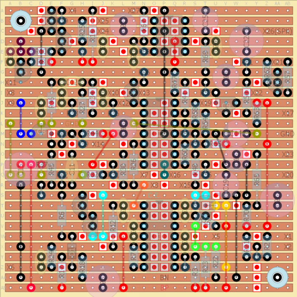
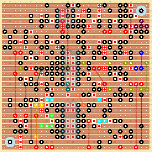
WARNING! All layouts in this thread contain errors and mistakes and neither of them is final. Once I build the unit I will be able to make a correct layout, but until then if you wish to build this keep an eye open for mistakes and check everything. Thanks:)
Ok, so this is what I came up with. I know that it's insanely crowded and it'll be a pain to build it, but I need to fit it in a box I have. It's area (2,9 x 2,9 inch ~ 7,3 x 7,3 cm) is like the half of Ray's PCB, so I'm a bit worried about crosstalk but I hope it's gonna be all right.
I'm also sorry about the crazy jumpering, but I couldn't find a better way to connect C13 and C14 (virtual ground) and also I think sockets (or plain IC-s) have the space under them for wires (for BN bus and X16 connection). Also if you can't connect two jumper wires into the same hole you may have to find a solution yourself, sorry about that.
Also note the legs of Q3, Q8 and Q9 - they are bent a bit.
I checked it a few times but of course there might be mistakes (it's very likely).
I created it using diy layout creator (http://diylc.org/) and I'm attaching the layout file too, so you can redesign, change or correct it if it's necessary.
I'm still waiting for components, so I can't verify that it's working (probably till the middle of April), but if you have the courage, try and build it:)
And of course if anyone spots any mistake, or has any comments, please say it. It's my first stripboard desing, so I know it could be done better (like less crowded )
cheers!
ben
edit, ps: In Ray's PCB the big electrolytic caps have 0,2" lead spacing, but mine are all 0,1", so I designed for them. Also note that legs of C14, C19 and C25 are not in adjacent lugs.
| Description: |
|
| Filesize: |
240.75 KB |
| Viewed: |
937 Time(s) |
| This image has been reduced to fit the page. Click on it to enlarge. |

|
| Description: |
|
| Filesize: |
120.12 KB |
| Viewed: |
765 Time(s) |
| This image has been reduced to fit the page. Click on it to enlarge. |

|
| Description: |
|
| Filesize: |
331.16 KB |
| Viewed: |
780 Time(s) |
| This image has been reduced to fit the page. Click on it to enlarge. |

|
| Description: |
|
| Filesize: |
152.96 KB |
| Viewed: |
787 Time(s) |
| This image has been reduced to fit the page. Click on it to enlarge. |
|
| Description: |
|

Download |
| Filename: |
toaster.zip |
| Filesize: |
11.45 KB |
| Downloaded: |
743 Time(s) |
Last edited by bence on Wed Apr 24, 2013 2:17 am; edited 3 times in total |
|
|
Back to top
|
|
|
bence
Joined: Jan 12, 2013
Posts: 17
Location: Budapest, Hungary
|
| Posted: Mon Apr 15, 2013 4:50 am Post subject:
|
|
|
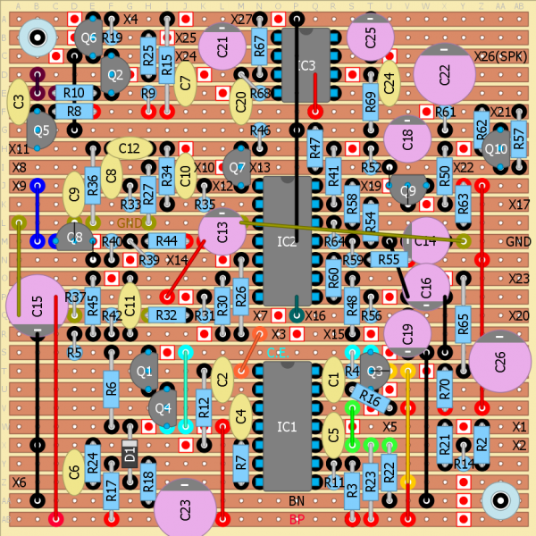
I've finished soldering in the jumpers, resistors and IC sockets and I spotted a few errors. Firstly, I forgot to put R16 on the stripboard layout (its between Q3 collector and BP). Luckily there's space for it (there's a hole between Q3-C and C1, and just under that stripe there's BP), but it has to stand. The other mistake is that C21 is a non-polarized electrolytic cap but I drew it as a ceramic.
Anyway the resistors fit in nicely, though a few has to stand. But you can use 1/8W resistors (except maybe for the ones <1k) and then it's less crowded. |
|
|
Back to top
|
|
|
fluxmonkey
Joined: Jun 24, 2005
Posts: 708
Location: cleve
|
| Posted: Mon Apr 15, 2013 4:53 pm Post subject:
|
|
|
really impressive stripboard, but i have wonder if the trouble is worth it, given the low price of the MFOS board...
_________________
www.fluxmonkey.com |
|
|
Back to top
|
|
|
bence
Joined: Jan 12, 2013
Posts: 17
Location: Budapest, Hungary
|
| Posted: Tue Apr 16, 2013 1:04 am Post subject:
|
|
|
If you compare it to other mfos boards, it is kinda cheap, but this way it's more cheaper:) plus I live in the UK and didn't want to spend much on the shipping.
Aaand this is really doityourself:)
I plan to enclosure this into a starbucks tea metal box, but I don't have a drill yet. |
|
|
Back to top
|
|
|
bence
Joined: Jan 12, 2013
Posts: 17
Location: Budapest, Hungary
|
| Posted: Tue Apr 16, 2013 7:01 am Post subject:
|
|
|
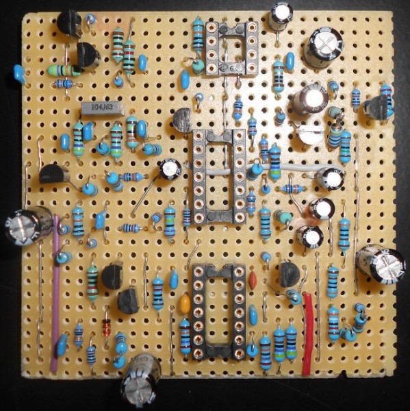
I still need to buy the bipolar 1uF caps and some kind of socket for the noise transistor (Q5), so I can experiment with different ones, but otherwise I soldered in all the components. Spotted another mistake: C22 (top right) was labeled C15 and was placed incorrectly. Here's an updated layout with C22 corrected and R16 shown and also a pic of my board. I used what I had, that's why the different resistors and caps. I didn't have some of the values, so there I used two resistors in series, which is ugly but who cares:)
| Description: |
|
| Filesize: |
220.75 KB |
| Viewed: |
790 Time(s) |
| This image has been reduced to fit the page. Click on it to enlarge. |
|
| Description: |
|
| Filesize: |
155.62 KB |
| Viewed: |
848 Time(s) |
| This image has been reduced to fit the page. Click on it to enlarge. |
|
|
|
|
Back to top
|
|
|
marvkaye
Joined: Mar 14, 2011
Posts: 225
Location: Fla
|
| Posted: Tue Apr 16, 2013 7:02 pm Post subject:
Re: noise toaster stripboard |
|
|
;Mr. Bence... in your stripboard post you said
| bence wrote: | | edit, ps: In Ray's PCB the big electrolytic caps have 0,2" lead spacing, but mine are all 0,1", so I designed for them. Also note that legs of C14, C19 and C29 are not in adjacent lugs. |
I have looked at your SB layout multiple times and for the life of me can't see C29. Am I C29 blind or did you mean something else? Hoping for the latter.......
<marv> |
|
|
Back to top
|
|
|
analog_backlash

Joined: Sep 04, 2012
Posts: 393
Location: Aldershot, UK
Audio files: 21
|
| Posted: Wed Apr 17, 2013 6:45 am Post subject:
Re: noise toaster stripboard |
|
|
| marvkaye wrote: | ;Mr. Bence... in your stripboard post you said
| bence wrote: | | edit, ps: In Ray's PCB the big electrolytic caps have 0,2" lead spacing, but mine are all 0,1", so I designed for them. Also note that legs of C14, C19 and C29 are not in adjacent lugs. |
I have looked at your SB layout multiple times and for the life of me can't see C29. Am I C29 blind or did you mean something else? Hoping for the latter.......
<marv> |
Looking at the MFOS schematics and BOM, the capacitors only go up to 26, so I think C29 should say C26. Even if you add Ray's 2 additional external inputs, that only adds one 0.1uF capacitor. I can't find C17 on the stripboard layout, but that's possibly because it can be wired directly across S7.
Gary
EDIT
Just looked at the panel wiring diagram and C17 is indeed wired across S7! |
|
|
Back to top
|
|
|
bence
Joined: Jan 12, 2013
Posts: 17
Location: Budapest, Hungary
|
| Posted: Wed Apr 17, 2013 2:17 pm Post subject:
|
|
|
| Sorry guys, I meant C25 instead of C29. C26's legs are in adjacent lugs. |
|
|
Back to top
|
|
|
marvkaye
Joined: Mar 14, 2011
Posts: 225
Location: Fla
|
| Posted: Wed Apr 17, 2013 6:21 pm Post subject:
|
|
|
| bence wrote: | | Sorry guys, I meant C25 instead of C29. C26's legs are in adjacent lugs. |
Whew, that's a relief. I was afraid that C29's were suddenly invisible to me.
I wonder if there's a way to make the components on the top view of the board partially transparent with that layout editor??? Figuring out which holes the leads of the electrolytics go to with them fully opaque is a bit of a chore. Not complaining, just wondering is all. Thanks for doing this, BTW.
<marv> |
|
|
Back to top
|
|
|
bence
Joined: Jan 12, 2013
Posts: 17
Location: Budapest, Hungary
|
|
|
Back to top
|
|
|
marvkaye
Joined: Mar 14, 2011
Posts: 225
Location: Fla
|
| Posted: Thu Apr 18, 2013 9:16 am Post subject:
|
|
|
| bence wrote: | Yeah Marv, you are totally right, I should've made a picture that way, too. Anyway, here it is.
And no problem at all, I mainly do this for myself, just thought I could share it. |
Thank you, bence... your effort is much appreciated.
| bence wrote: | | Though consider the fact that's it not finished nor tested yet, so I can't tell if this layout works or not. Or even if it does and everything is connected to the right place, there might be crosstalk and other unwanted effects. So for the best results get Ray's PCB:) |
I understand completely and am happy for the warning that it's untested. I generally just buy Ray's PCBs because they're reasonably priced and I want to support him to make sure he keeps doing what he does. It'd be terrible to have him pack up and disappear. However, I do enjoy fiddling with stripboards... I find laying them out and checking them against the schematics sort of therapeutic, it's a zen thing I guess. And since my PCB layout skills are not very polished SB lets me get circuits sort of permanently built without the PCB pain. One of these days, though, I'm taking that next step... just need the time to devote to it.
Anyway, thanks again... be sure to let us know if it works after you've tested it.
<marv> |
|
|
Back to top
|
|
|
Allison
Joined: Apr 23, 2013
Posts: 6
Location: Washington, Dc
|
| Posted: Tue Apr 23, 2013 7:59 pm Post subject:
|
|
|
I'm new to this, so this may be a stupid observation. But, I've been trying to troubleshoot a breadboard layout of just the expo converter and the VCO, when I came across this post. I've been looking at your layout and noticed a few things
Pin 3 of IC1 doesn't seem to connect to the virtual ground.
Pin 11 of IC 1 doesn't seem to be connected to BN.
These observations may be a result of my own ignorance, so if I'm confused, please let me know. |
|
|
Back to top
|
|
|
bence
Joined: Jan 12, 2013
Posts: 17
Location: Budapest, Hungary
|
| Posted: Wed Apr 24, 2013 12:37 am Post subject:
|
|
|
Hello and thanks for the feedback:)
IC1 pin3 is connected to pin12, and therefore virtual ground, because the strip there under the IC is not broken (check it on the last pic).
However you are right about pin11, I did mess that up (and there's no space for correcting it nicely) 
I reorganized that part of the layout a few times and I must have forgot to place that link again..
Thanks for noticing it, I wonder how many other serious mistakes are still there. And sorry for the low quality :/ |
|
|
Back to top
|
|
|
Allison
Joined: Apr 23, 2013
Posts: 6
Location: Washington, Dc
|
| Posted: Wed Apr 24, 2013 8:21 pm Post subject:
|
|
|
| I totally ignored the pic showing the broken links under the chips. Glad I at least provided some useful input! I still can't get my breadboarded expo converter and VCO to work... |
|
|
Back to top
|
|
|
Nardu

Joined: Feb 28, 2011
Posts: 62
Location: Braila, Romania
|
|
|
Back to top
|
|
|
bence
Joined: Jan 12, 2013
Posts: 17
Location: Budapest, Hungary
|
| Posted: Mon May 20, 2013 2:22 pm Post subject:
|
|
|
Hi all!
Nardu that's a nice and tidy layout, not like mine:D
I finally managed to finish this. There's one serious mistake in my layout: I haven't connected the top (6th row) and bottom BP bus.. I found this out after assembly, so I solved it with a wire on the soldering side, which is not nice. Otherwise it's working and making beautiful sounds, with a low crosstalk from the lfo, but that could be because of the panel wiring or the power distribution, too. I noticed that even when powering it from a regulated supply the controls interact with each other in a bad way (like turning up the volume or hitting a harmonics with the filter drops BP voltage hence vco freq and stuff like this:)). But I remember Ray mentioned the lo-fi-ness of this unit, so this was no big surprise and I love the thing anyway:)
I added a dc input and an attenuated earphone out (drived by the 386).
I also added an external CV input and a pot for the VCO, an input for the VCF and a gate input (I plan to build a simple 8step seq).
I don't know if I will make a proper layout later, maybe if I have time..
but the price difference is probably not worth the trouble, so buying Ray's PCB is a good idea...and then you still have to populate, wire and make a case, so plenty of DIY left:D
anyway...pics of my toaster:
http://imgur.com/a/xfdnZ
(still missing 4 screws for the speaker /now hold by superglue:D/ and labels for the controls)
it's a bit crowded in the inside (the speaker magnet is pushing the stripboard:/), if I could do this again I would drill a few holes a bit differently:)
another thing I noticed is the asymmetrical behaviour of the ARG-VCA: a long attack and a short release is much more powerful than a short attack and a long release, the latter is barely a not-so-loud pop. it could be the design, or a mistake in my build? a scope would be handy now:)
also, the VCA seems to offset the dc: when I connected it to a stereo the speakers moved in and out (a lot...looked cool but also a bit scary) according to the VCA's volume...it's like the decoupling cap does not work (or the change is not slow enough for the cap to block? sorry for the rambling)
ben |
|
|
Back to top
|
|
|
Varoudis
Joined: Dec 03, 2009
Posts: 31
Location: London
|
Posted: Tue Feb 25, 2014 1:22 am Post subject:
 |
|
|
Hi all, sorry for getting this back from the dead!
I ordered the components from Farnell (waiting delivery today) and Ill give it a try in a stripboard!
At the moment my workbench is not fully equipped (scope, bench power or super cool multi, just a basic one) but I think it wouldn't be a problem.
As a goal, Im aiming to start building a modular synth (Ill get the MFOS PCBs) after easter. So Im after a Rigol scope and a nice Fluke multi at some point.
Thanks for the stripboards guy! Much appreciated! |
|
|
Back to top
|
|
|
Varoudis
Joined: Dec 03, 2009
Posts: 31
Location: London
|
| Posted: Sat Mar 01, 2014 4:02 am Post subject:
|
|
|
| btw! Anyone tested the stripboard versions in this page?!?! |
|
|
Back to top
|
|
|
bence
Joined: Jan 12, 2013
Posts: 17
Location: Budapest, Hungary
|
| Posted: Sat Mar 08, 2014 10:27 am Post subject:
|
|
|
| Varoudis wrote: | | btw! Anyone tested the stripboard versions in this page?!?! |
Hi!
Yes I built my toaster based on this layout. However as I said in the opening post there are mistakes in my layout which I discovered while building and testing the unit. But if you read this topic, you will know of all the mistakes and so you can correct them. (the worst mistake I made is a missing link in the BP bus that I already mentioned) |
|
|
Back to top
|
|
|
Varoudis
Joined: Dec 03, 2009
Posts: 31
Location: London
|
| Posted: Mon Mar 10, 2014 7:20 am Post subject:
|
|
|
| bence wrote: | | Varoudis wrote: | | btw! Anyone tested the stripboard versions in this page?!?! |
Hi!
Yes I built my toaster based on this layout. However as I said in the opening post there are mistakes in my layout which I discovered while building and testing the unit. But if you read this topic, you will know of all the mistakes and so you can correct them. (the worst mistake I made is a missing link in the BP bus that I already mentioned) |
Hi, thanks for the reply.
By skimming through the topic I left with the impression that your were 'working on the board but not yet completed' so I ask in order to get an upodated/complete view. (Sorry, maybe it was because Im not a native in Eng)
I have ordered the PCB but Ill try to play with the stripborad untill I get it in the mail.
Thanks |
|
|
Back to top
|
|
|
bence
Joined: Jan 12, 2013
Posts: 17
Location: Budapest, Hungary
|
| Posted: Mon Mar 10, 2014 7:37 am Post subject:
|
|
|
Well I finished a toaster based on that layout, but since the layout has a few errors I had to fix them when troubleshooting the finished unit. Anyway I wrote all the fixes here, so you should be able to build this based on the info in this topic.
When I was building this I was thinking about making a proper, bug-free, less crowded layout, but I never did:)
Instead I made a 8-step sequencer for the toaster.
Check out how it sounds (it sounds ugly:D) |
|
|
Back to top
|
|
|
Varoudis
Joined: Dec 03, 2009
Posts: 31
Location: London
|
| Posted: Mon Mar 10, 2014 7:39 am Post subject:
|
|
|
| bence wrote: | Well I finished a toaster based on that layout, but since the layout has a few errors I had to fix them when troubleshooting the finished unit. Anyway I wrote all the fixes here, so you should be able to build this based on the info in this topic.
When I was building this I was thinking about making a proper, bug-free, less crowded layout, but I never did:)
Instead I made a 8-step sequencer for the toaster.
Check out how it sounds (it sounds ugly:D) |
heheh! Nice! |
|
|
Back to top
|
|
|
earlneath
Joined: Oct 13, 2018
Posts: 1
Location: Australia
|
| Posted: Sat Oct 13, 2018 6:53 am Post subject:
Re: MFOS Noise Toaster stripboard in Lochmaster |
|
|
| Nardu wrote: | - Here is the stripboard layout in Lochmaster using a H25SR050 stripboard (2x4 inch)
- Still working. Mising: Q10,R57,R61,R62,X21,X22. If I fail, I will use a H25SR075 stripboard. |
Hi Nardu
After this time I am not sure if you can recall but your design looks good and I'm wondering whether you implemented with those missing items, or alternatively what your solution was?
Thanks in advance! |
|
|
Back to top
|
|
|
|

 Forum index » DIY Hardware and Software » MusicFromOuterSpace.com designs by Ray Wilson