| Author |
Message |
acidblue
Joined: Jun 26, 2009
Posts: 226
Location: The Darkside
|
|
|
Back to top
|
|
 |
ezekiel
Joined: Oct 17, 2009
Posts: 30
Location: Columbus Ohio
|
 Posted: Mon Jun 06, 2011 11:36 am Post subject: Posted: Mon Jun 06, 2011 11:36 am Post subject:
|
  |
|
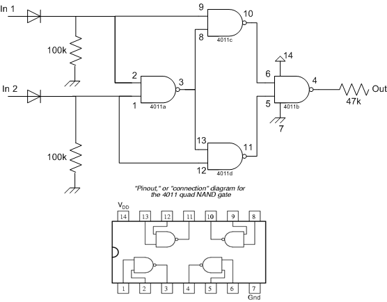
The schematic you show with the four 4011 gates is really XOR. I am not sure what effect the diodes on inputs would have.
For pseudo-ringmod, I like to use the 4030 or 4070 or 4077 chips (XOR and XNOR)--that only requires one gate. Then, you can combine more XOR gates together in whatever configurations you can think of.
Another approach is four diodes in a bridge-rectifier square.
Replace the 4011 with a 4093 (Schmitt-input NAND gates) for yet another variation.
If you are feeding in the 4069 triangle oscillator, it might not come out according to the textbook XOR binary/boolean function. However, in Lunetta land, anything goes--just report here any interesting surprises! |
|
|
Back to top
|
|
|
inlifeindeath

Joined: Apr 02, 2010
Posts: 316
Location: Albuquerque, NM
|
| Posted: Mon Jun 06, 2011 3:24 pm Post subject:
|
|
|
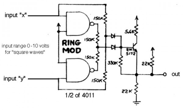
i'm pretty positive the schem you posted is the circuit i put in my lunetta. you get the more classic ringmod sound when you feed hi frequency square waves in to the input, and then modulate one or both inputs. the diodes are there so no current is feeding back into the oscillators. i believe i used a buffered 4011 hence the little o. don't know if it makes any difference.
_________________
http://www.youtube.com/user/borisandfef |
|
|
Back to top
|
|
|
acidblue
Joined: Jun 26, 2009
Posts: 226
Location: The Darkside
|
| Posted: Mon Jun 06, 2011 4:05 pm Post subject:
|
|
|
I'll have to try some experimenting with this.
Maybe try some square wave VCO's, and see if there is a difference.
Like to to try some other chips as well for a ring mod, might
have a couple of 4070's laying around, I'll have to look.
Back to the lab for more diabolical Lunetta fun! |
|
|
Back to top
|
|
|
tjookum

Joined: May 25, 2010
Posts: 360
Location: Netherlands
Audio files: 26
|
| Posted: Tue Jun 07, 2011 3:17 am Post subject:
|
|
|
| Quote: | | he schematic you show with the four 4011 gates is really XOR. |
personally I never really understood why everyone keeps using the 4011 ringmod, it's just a complex way of making a XOR. You can get a 4070 for the same money and have 4 of them.
_________________
There he goes. One of God's own prototypes. A high-powered mutant of some kind never even considered for mass production. Too weird to live, and too rare to die.
Hunter S. Thompson
movies
noise |
|
|
Back to top
|
|
|
RF

Joined: Mar 23, 2007
Posts: 1502
Location: Northern Minnesota, USA
Audio files: 28
|
|
|
Back to top
|
|
|
inlifeindeath
Joined: Apr 02, 2010
Posts: 316
Location: Albuquerque, NM
|
| Posted: Tue Jun 07, 2011 1:12 pm Post subject:
|
|
|
| tjookum wrote: | | Quote: | | he schematic you show with the four 4011 gates is really XOR. |
personally I never really understood why everyone keeps using the 4011 ringmod, it's just a complex way of making a XOR. You can get a 4070 for the same money and have 4 of them. |
Simple... had a 4011, didn't have a 4070 
Also I LOVE doing extra work for the same effect.
_________________
http://www.youtube.com/user/borisandfef |
|
|
Back to top
|
|
|
Psyingo

Joined: Jun 11, 2009
Posts: 248
Location: Canada
|
| Posted: Tue Jun 07, 2011 1:41 pm Post subject:
|
|
|
| inlifeindeath wrote: | | tjookum wrote: | | Quote: | | he schematic you show with the four 4011 gates is really XOR. |
personally I never really understood why everyone keeps using the 4011 ringmod, it's just a complex way of making a XOR. You can get a 4070 for the same money and have 4 of them. |
Simple... had a 4011, didn't have a 4070
Also I LOVE doing extra work for the same effect. |
i also have a ton of 4011's and no 4070. i've had a hard time finding them for cheap. |
|
|
Back to top
|
|
|
mono-poly

Joined: Jul 07, 2004
Posts: 937
Location: Rotterdam, Netherlands
Audio files: 2
|
| Posted: Sat Feb 15, 2020 7:31 pm Post subject:
|
|
|
if i feed this circuit with my cd40106 square vco's i barely get any gain at my output signal.
 |
|
|
Back to top
|
|
|
Sven
Joined: Mar 10, 2017
Posts: 49
Location: Norway
|
| Posted: Sun Feb 16, 2020 5:52 am Post subject:
Re: Questions about 4011 Ring Mod |
|
|
| acidblue wrote: |
Also my understanding of ring mods is you need to use 2 different inputs, like 2 VCO"S or other OSC's, you can't use the
same VCO into both inputs, is this correct? |
Hi,
no this is not correct. A ringmodulator fed with the same signal on both inputs is a frequency doubler.¨Not sure if this applies to the 4011 "pseudo" ringmod.
73 Sven |
|
|
Back to top
|
|
|
JovianPyx

Joined: Nov 20, 2007
Posts: 1988
Location: West Red Spot, Jupiter
Audio files: 224
|
| Posted: Sun Feb 16, 2020 6:32 am Post subject:
Re: Questions about 4011 Ring Mod |
|
|
| Sven wrote: | | no this is not correct. A ringmodulator fed with the same signal on both inputs is a frequency doubler.¨Not sure if this applies to the 4011 "pseudo" ringmod. |
As you wrote, this is a pseudo ringmod. If you look at the binary truth table for an XOR it does a binary multiplication of sorts, but it receives only two states and outputs only two states. A true audio ring modulator is an analog multiplier chip. So while the two are related by the multiply operation, the similarity ends there. Also, the theory behind frequency doubling with a ring mod comes from the trig identity surrounding sin(x)^2 and sin(2x). This means that the frequency doubling is purest when the inputs are both the same sine. Waveforms that differ from sine have less and less frequency doubled output. As such, we cannot expect the 4011 version to do all of the things that are described for an analog ringmod. The 4011 or XOR type is useful, just very different. Also, within the frame of analog multipliers there are 3 kinds - single quadrant, two quadrant and four quadrant. Only the four quadrant type is a true analog ring modulator.
It should also be noted that the term "ring" comes from the original circuit which was used in radio electronics to mix RF signals. It was composed of a transformer connected ring of diodes. The term has nothing to do with a ringing sound. This type of ring modulator has been used by some in synth electronics, the main complaint being that you need special diodes and a large input signal. The effect is also different from a four quadrant multiplier.
_________________
FPGA, dsPIC and Fatman Synth Stuff
Time flies like a banana.
Fruit flies when you're having fun.
BTW, Do these genes make my ass look fat?
corruptio optimi pessima
|
|
|
Back to top
|
|
|
Sven
Joined: Mar 10, 2017
Posts: 49
Location: Norway
|
| Posted: Sun Feb 16, 2020 6:53 am Post subject:
Re: Questions about 4011 Ring Mod |
|
|
| JovianPyx wrote: |
It should also be noted that the term "ring" comes from the original circuit which was used in radio electronics to mix RF signals. It was composed of a transformer connected ring of diodes. The term has nothing to do with a ringing sound. This type of ring modulator has been used by some in synth electronics, the main complaint being that you need special diodes and a large input signal. The effect is also different from a four quadrant multiplier. |
I have build some classic ringmodulators mostly for Shortwave radios and I was experimenting with "real" ringmods for audio. One input an Yamaha organ and the other a sinewave from a audio signal generator made nice bell sounds. |
|
|
Back to top
|
|
|
JovianPyx
Joined: Nov 20, 2007
Posts: 1988
Location: West Red Spot, Jupiter
Audio files: 224
|
| Posted: Sun Feb 16, 2020 7:09 am Post subject:
|
|
|
Analog ringmods are often used to make bell-like sounds because of the harmonics they produce.
This is also true of FM used for bells.
However, in both of those cases, there is no ringing as there is in a real metal bell.
With a metal bell, you strike it and then it rings out from resonance. It needs only the impact energy to ring. An FM or ringmod created bell circuit won't do that, it requires the input remain and then an EG and VCA are used to cause the fade out.
The "ring" sound that you don't hear from the XOR version is because it isn't producing the harmonics that make the real ringmod sound bell-like.
It is unfortunate that the term "ring" is applied because it is quite confusing since it has two meanings in this context which is why I gave a bit of it's semantic history.
_________________
FPGA, dsPIC and Fatman Synth Stuff
Time flies like a banana.
Fruit flies when you're having fun.
BTW, Do these genes make my ass look fat?
corruptio optimi pessima
|
|
|
Back to top
|
|
|
Sven
Joined: Mar 10, 2017
Posts: 49
Location: Norway
|
| Posted: Sun Feb 16, 2020 7:27 am Post subject:
|
|
|
Thank you for the explanations  |
|
|
Back to top
|
|
|
JovianPyx
Joined: Nov 20, 2007
Posts: 1988
Location: West Red Spot, Jupiter
Audio files: 224
|
| Posted: Sun Feb 16, 2020 7:42 am Post subject:
|
|
|
| Sven wrote: | | Thank you for the explanations |
You are very welcome 
_________________
FPGA, dsPIC and Fatman Synth Stuff
Time flies like a banana.
Fruit flies when you're having fun.
BTW, Do these genes make my ass look fat?
corruptio optimi pessima
|
|
|
Back to top
|
|
|
dk
Joined: Feb 12, 2019
Posts: 115
Location: Europe
|
| Posted: Sun Apr 26, 2020 9:55 am Post subject:
|
|
|
Out of curiosity, would it be easy to create a "real" ring mod then out of the circuit toward the bottom of this page? (the one without transformers)
Taking a shot at it, we'd have to sum the 2 signals and feed to W1, sum the 2 signals with the carrier reversed in polarity and feed it to W2, and then hook up a differential amplifier to +1 and -1 to get the output? |
|
|
Back to top
|
|
|
JovianPyx
Joined: Nov 20, 2007
Posts: 1988
Location: West Red Spot, Jupiter
Audio files: 224
|
| Posted: Sun Apr 26, 2020 3:35 pm Post subject:
|
|
|
Well, as always, I'll say "try it".
Yes, it will "work". No, it will not sound like a "true" ring modulator (whatever that is).
In fact, there is no such thing as a "true" ring modulator at this point in time. The term has been mash and squished into so many different things that one can't know what it is just by hearing "ring modulator". In some circles (synth), the "true" ring modulator is a 4 quadrant multiplier like MC1496. In other circles (amateur radio) a ring modulator is one that has the diodes and transformers. Many alternate approximations have been designed to attempt to do the same things and in some respects they do.
With the diode and resistor one, you want to use diodes that have very low "on" voltage. Schottky type should work. You also want to hit it with as large of input signals as you can without blowing the diodes. Doing so limits the switching distortion caused by the diodes turning on and off and the signal multiplication effect should be more apparent.
Depending on what kinds of sounds you're looking for, maybe experimenting with different diodes will help. In that case, I'd try Schottky, silicon signal diodes (like 1N4148), germanium (1N34A), silicon power diodes, selenium rectifier diodes and LEDs.
So I'd amplify as much as I can, then put it through the modulator and then attentuate back down to normal signal levels.
_________________
FPGA, dsPIC and Fatman Synth Stuff
Time flies like a banana.
Fruit flies when you're having fun.
BTW, Do these genes make my ass look fat?
corruptio optimi pessima
|
|
|
Back to top
|
|
|
gabbagabi

Joined: Nov 29, 2008
Posts: 652
Location: Berlin by n8
Audio files: 23
|
|
|
Back to top
|
|
|
dk
Joined: Feb 12, 2019
Posts: 115
Location: Europe
|
| Posted: Mon Apr 27, 2020 2:11 am Post subject:
|
|
|
Thanks for the insight Jovian! As soon as I free up my breadboard, I may just give it a shot.
Gabbagabi, you mean that your sub circuit would not suffer from impedance problems, or what I had posted? |
|
|
Back to top
|
|
|
PHOBoS

Joined: Jan 14, 2010
Posts: 5609
Location: Moon Base
Audio files: 705
|
| Posted: Mon Apr 27, 2020 2:25 am Post subject:
|
|
|
| gabbagabi wrote: | (sorry for posting opamps in the lunetta forum again  ) ) |
Burn the witch! 
interesting, I am not quite awake yet but I think I should be able to do those things with The Toggler. Too bad I can't test right now.
For the one with just the diodes I wonder if it would make sense to use those opamp based ideal diode circuits.
Oh shit, now I mentioned opamps too, I guess it is self-immolation time.
_________________
"My perf, it's full of holes!"
http://phobos.000space.com/
SoundCloud BandCamp MixCloud Stickney Synthyards Captain Collider Twitch YouTube |
|
|
Back to top
|
|
|
gabbagabi
Joined: Nov 29, 2008
Posts: 652
Location: Berlin by n8
Audio files: 23
|
| Posted: Mon Apr 27, 2020 4:21 am Post subject:
|
|
|
rofl, yeah burn it!
although one must be carefull with burning east-germans - u know that we come from a highly contaminated part of the past, better consult the ministry of radiation before start buying the gasoline 
dunno either if the toggler would do the job, probably yes?
the rectifier idea is not a bad one, if u analyse the fonitronic rm it is also based on two rectifiers http://electro-music.com/forum/topic-39762.html,
after messing around with the fonitronik circuit in the simulator, i came up with the attached circuit, the output wave form is not what we would expect from a "real" RM (same with the fonitronic RM) but the spectrum analysis shows the typical two peaks, one at 8khz and one at 10khz, input was 1khz and 9khz, the output is also unipolar - so one should apply a decoupling C/R or may a static offset.
@denmark i meant "my" circuit would not suffer
please let me know if iam to offtopic, but i personally love it to see different approaches to the same goal
| Description: |
|
| Filesize: |
55.81 KB |
| Viewed: |
327 Time(s) |
| This image has been reduced to fit the page. Click on it to enlarge. |

|
|
|
|
Back to top
|
|
|
dk
Joined: Feb 12, 2019
Posts: 115
Location: Europe
|
| Posted: Mon Apr 27, 2020 5:03 am Post subject:
|
|
|
Thanks for posting that gabbagabi... the right half of Fonik's circuit is sort of similar to what I had in mind, but simpler and (probably) better.
As for burning east-germans, we're all wearing masks these days, so it might be less of a problem than it usually would be
I feel like half my posts are OT here, but it's great to learn from you guys, even if it involves ::gasps:: opamps and transistors! |
|
|
Back to top
|
|
|
|

 Forum index » DIY Hardware and Software » Lunettas - circuits inspired by Stanley Lunetta