| Author |
Message |
mike page

Joined: Sep 26, 2016
Posts: 134
Location: norwich, uk
|
 Posted: Mon Nov 28, 2016 4:29 am Post subject:
saw straight out of a 4046 bodge Posted: Mon Nov 28, 2016 4:29 am Post subject:
saw straight out of a 4046 bodge |
  |
|
If you set a simple 4046 vco (like the one on hackaday) but put two capacitors in series for the timing cap, then measure the junction between them you have a good solid rising saw!
Try it out! |
|
|
Back to top
|
|
 |
PHOBoS

Joined: Jan 14, 2010
Posts: 5603
Location: Moon Base
Audio files: 705
|
|
|
Back to top
|
|
|
mike page
Joined: Sep 26, 2016
Posts: 134
Location: norwich, uk
|
| Posted: Mon Nov 28, 2016 2:28 pm Post subject:
|
|
|
Ah cool! I wasnt planning on putting a buffer on my VCO in. Would you recommend it? Also (sorry if this is a silly question but) what does this do in tracker mode? Do you send a squared up audio source in and it latches to the pitch? Oh and what does the xor out do?!
Cheeerzzz |
|
|
Back to top
|
|
|
Cfish

Joined: Feb 24, 2016
Posts: 477
Location: Indiana
|
| Posted: Mon Nov 28, 2016 5:16 pm Post subject:
|
|
|
Nice. mike. Just tried it.
I'm going on to try the Schematic PhoBos posted too.
Can anyone point me at the reason for using u1a as a ground reference that way? Don't think I have ever seen that done before. |
|
|
Back to top
|
|
|
PHOBoS
Joined: Jan 14, 2010
Posts: 5603
Location: Moon Base
Audio files: 705
|
| Posted: Mon Nov 28, 2016 6:49 pm Post subject:
|
|
|
| mike page wrote: | | Ah cool! I wasnt planning on putting a buffer on my VCO in. Would you recommend it? |
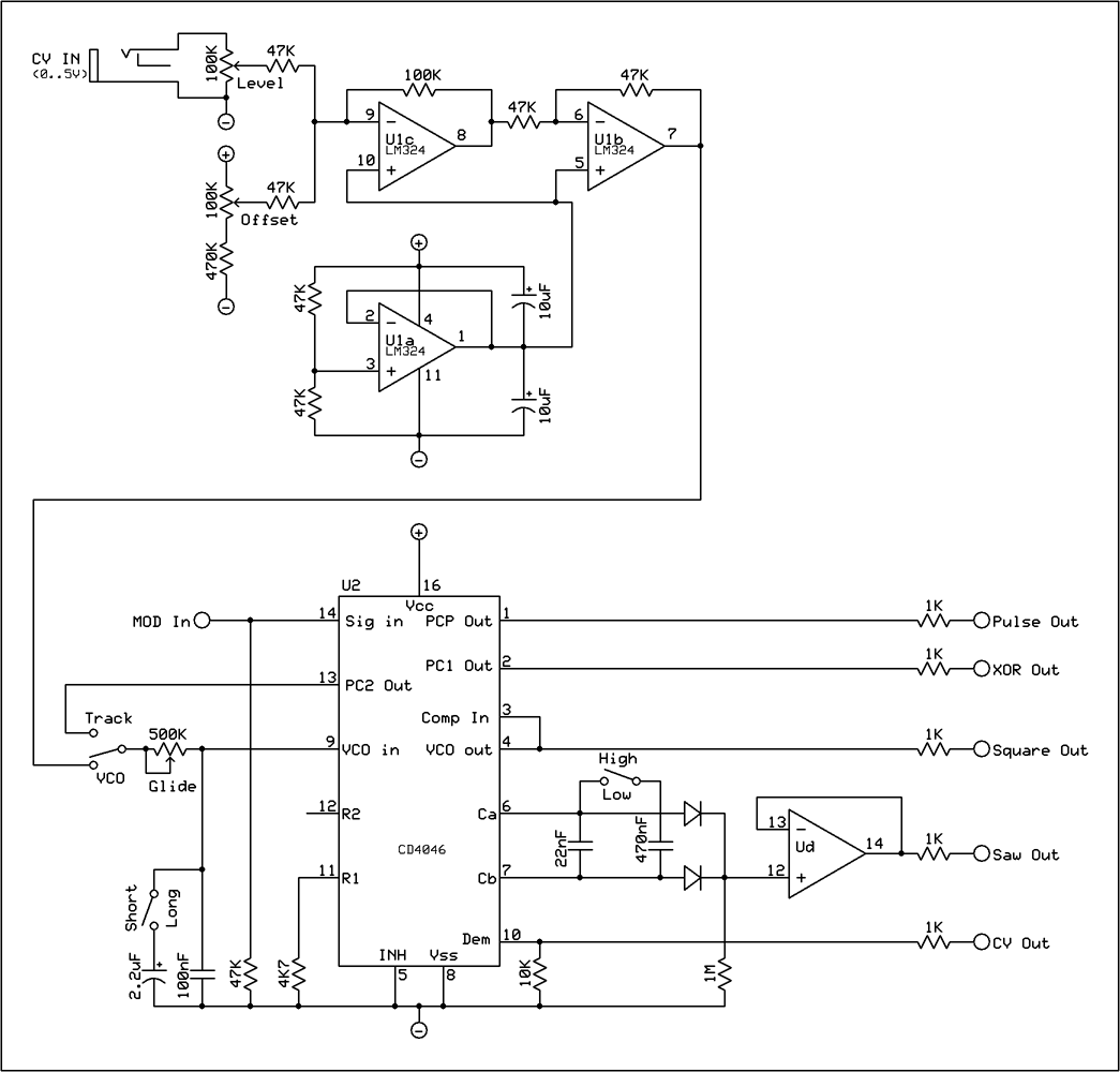
well, it is not just a buffer although it does buffer it as well. The first stage (U1c) is a voltage summing amplifier or adder which adds the CV
with the offset voltage. Without a CV signal I can control the frequency with the offset control and with a CV signal I can add (you probably
guessed it) an offset voltage. However it does invert so the second stage (U1b) inverts it again so that a positive CV signal gives a higher
frequency. The schematic I posted is the VCO I used in my modular lunetta which is powered by a single supply, so the - is just the GND
connection. However a summing amplifier does need a reference voltage to work properly which is provided by U1a.
note: I later changed the circuit by connecting the level pot to this reference voltage as well instead of - which gives a much better control.
The way it is drawn in the schematic it would actually have an effect on the frequency when nothing was connected to it.
| Quote: | | Also (sorry if this is a silly question but) what does this do in tracker mode? Do you send a squared up audio source in and it latches to the pitch? |
yep that is what it does, or at least it tries to latch on to it but usually fails miserably, creating a very nice effect and with the glide control you
can add a sort of wobble to it. (you can hear that in the track BugSquatch although for that one I used the wogglebug, hence the title, but it is the same principle)
| Quote: | | Oh and what does the xor out do?! |
The XOR out uses the internal XOR gate as a digital ringmod which works together with the signal on the mod. input. pin 3 is the other input
which is hardwired to the output of the VCO.
_________________
"My perf, it's full of holes!"
http://phobos.000space.com/
SoundCloud BandCamp MixCloud Stickney Synthyards Captain Collider Twitch YouTube |
|
|
Back to top
|
|
|
mike page
Joined: Sep 26, 2016
Posts: 134
Location: norwich, uk
|
| Posted: Tue Nov 29, 2016 3:12 am Post subject:
|
|
|
Awesome, what alot of fun crazy crap on one chip!
Thanks so much for the thorough run down really helpful.
I was just planning on summing a freq/offset pot and CV source through diode or resistor mixing.
Now if only there was a fool proof way of turning that saw into a triangle! |
|
|
Back to top
|
|
|
Cfish
Joined: Feb 24, 2016
Posts: 477
Location: Indiana
|
|
|
Back to top
|
|
|
mike page
Joined: Sep 26, 2016
Posts: 134
Location: norwich, uk
|
| Posted: Tue Nov 29, 2016 5:18 am Post subject:
|
|
|
| Ah cheers, I tried one of those and couldnt get it to work. I think im going to make digital stepped triangles instead and squish them with a capacitor. |
|
|
Back to top
|
|
|
Cfish
Joined: Feb 24, 2016
Posts: 477
Location: Indiana
|
| Posted: Tue Nov 29, 2016 5:23 am Post subject:
|
|
|
I'm just a hack, trying to get a better grip on this.
Till now I have stayed mostly in the analog realm.
Would love to see what you come up with. |
|
|
Back to top
|
|
|
gabbagabi

Joined: Nov 29, 2008
Posts: 652
Location: Berlin by n8
Audio files: 23
|
|
|
Back to top
|
|
|
JovianPyx

Joined: Nov 20, 2007
Posts: 1988
Location: West Red Spot, Jupiter
Audio files: 224
|
| Posted: Wed Dec 14, 2016 6:49 am Post subject:
|
|
|
| mike page wrote: | Ah cool! I wasnt planning on putting a buffer on my VCO in. Would you recommend it? Also (sorry if this is a silly question but) what does this do in tracker mode? Do you send a squared up audio source in and it latches to the pitch? Oh and what does the xor out do?!
Cheeerzzz |
I would recommend the buffer. This is a high impedance circuit, so any loading can cause waveform distortion and nonlinear response to CV. I'd suggest a FET input opamp like TL07x.
I like the notion of using two capacitors to get the saw, but I'd still recommend the buffer. It would also seem that "matched" caps will give the best balanced waveform, but I've no idea how much it would matter. Matching the caps would be just randomly trying different ones (of the same marked value) until you get the best waveform on an oscope.
_________________
FPGA, dsPIC and Fatman Synth Stuff
Time flies like a banana.
Fruit flies when you're having fun.
BTW, Do these genes make my ass look fat?
corruptio optimi pessima
|
|
|
Back to top
|
|
|
zloth
Joined: Nov 18, 2016
Posts: 12
Location: Augsburg, Bayern
|
| Posted: Tue Dec 20, 2016 2:13 pm Post subject:
|
|
|
Hello all, 1st post.
Been meaning to ask about the 4046, would it work if I put a chain of resistors between the positive voltage and the VCO so I could "play" it in a way similar to a stylophone? |
|
|
Back to top
|
|
|
Cynosure
Site Admin

Joined: Dec 11, 2010
Posts: 966
Location: Toronto, Ontario - Canada
Audio files: 82
|
| Posted: Tue Dec 20, 2016 6:21 pm Post subject:
|
|
|
How flat is this saw shape? Does it remain flat at low frequencies? Is it the same amplitude at high frequencies?
Could you post some scope shots at ~60Hz, ~440Hz, ~1000Hz, 2000Hz?
_________________
JacobWatters.com |
|
|
Back to top
|
|
|
PHOBoS
Joined: Jan 14, 2010
Posts: 5603
Location: Moon Base
Audio files: 705
|
| Posted: Tue Dec 20, 2016 6:30 pm Post subject:
|
|
|
| zloth wrote: | Hello all, 1st post.
Been meaning to ask about the 4046, would it work if I put a chain of resistors between the positive voltage and the VCO so I could "play" it in a way similar to a stylophone? |
you could do that but you probably need a resistor to GND too, so basically just a voltage divider with tabs, at least if you hook it up straight to the
4046 input. If you don't have a resistor to GND it would just control the current and with the 4046 being a CMOS chip the input is most likely very
high impedance and current control won't do very much.
 
_________________
"My perf, it's full of holes!"
http://phobos.000space.com/
SoundCloud BandCamp MixCloud Stickney Synthyards Captain Collider Twitch YouTube |
|
|
Back to top
|
|
|
zloth
Joined: Nov 18, 2016
Posts: 12
Location: Augsburg, Bayern
|
| Posted: Wed Dec 21, 2016 2:29 am Post subject:
|
|
|
Thanks for the quick reply!
Yes, I later realised I would need a resistor to GND as effectively what I'm doing is making a "stepped starve" control, so instead of having one lug of a pot going to GND I would need an equivalent.
Another manual control for a 4046 I had thought of was a R/2R with one or more inputs controlled by momentary switches. Would this even work?
Talking of which, has anyone tried using more unusual types of input clock, such as Shift Register or even 7-Segment Driver, to create polyrhythms for a DAC?
Sorry for all the questions, still quite new to all this, I'm very much a traditional synth/sequencer person (still use a Korg M1  )looking for something to inject a little delicious "live" chaos but a more exciting than a plain vanilla APC, although I have had fun with various 4093 configurations. )looking for something to inject a little delicious "live" chaos but a more exciting than a plain vanilla APC, although I have had fun with various 4093 configurations.
Thanks again. |
|
|
Back to top
|
|
|
J-chot
Joined: Jan 20, 2014
Posts: 44
Location: Decatur AL
|
| Posted: Sat Mar 28, 2020 2:18 am Post subject:
|
|
|
Hey, if I was running this off of a bipolar 12 volt supply, would I omit the U1a circuit and just tie 10 and 5 of the lm324 to ground?
Sorry to resurrect a dead thread, but it beats making a new one. |
|
|
Back to top
|
|
|
PHOBoS
Joined: Jan 14, 2010
Posts: 5603
Location: Moon Base
Audio files: 705
|
| Posted: Sat Mar 28, 2020 3:55 am Post subject:
|
|
|
yes, BUT the 4046 will likely not survive a bipolar 12V supply. It might depend on the manufacturer but the datasheet I have here
specifies a maximum voltage of 20V, so you could use a bipolar 9V supply. Also connect the level pot to the (fake) GND as I did here.
This way the level pot doesn't affect the frequency when nothing is connected to the CV input.
_________________
"My perf, it's full of holes!"
http://phobos.000space.com/
SoundCloud BandCamp MixCloud Stickney Synthyards Captain Collider Twitch YouTube |
|
|
Back to top
|
|
|
J-chot
Joined: Jan 20, 2014
Posts: 44
Location: Decatur AL
|
| Posted: Mon Mar 30, 2020 10:43 pm Post subject:
|
|
|
| Can I run the 4046 off of + 12 ground, but also use the CV circuitry/opamp as bipolar? |
|
|
Back to top
|
|
|
JovianPyx
Joined: Nov 20, 2007
Posts: 1988
Location: West Red Spot, Jupiter
Audio files: 224
|
| Posted: Tue Mar 31, 2020 5:30 am Post subject:
|
|
|
The schematic PHOBoS posted looks like it is set up to work with single supply. U1a is a virtual ground stabilizer. That circuit should work from +12 v. The + symbol on the schematic goes to +12 and the - symbol goes to PSU ground or zero volts.
_________________
FPGA, dsPIC and Fatman Synth Stuff
Time flies like a banana.
Fruit flies when you're having fun.
BTW, Do these genes make my ass look fat?
corruptio optimi pessima
|
|
|
Back to top
|
|
|
PHOBoS
Joined: Jan 14, 2010
Posts: 5603
Location: Moon Base
Audio files: 705
|
| Posted: Tue Mar 31, 2020 6:46 am Post subject:
|
|
|
| J-chot wrote: | | Can I run the 4046 off of + 12 ground, but also use the CV circuitry/opamp as bipolar? |
It depends a bit on the CV signals you want to use but you'll run the risk that the 4046 wil receive a negative voltage
on the CV input which it will not be happy with. There are ways to add an extra offset and prevent any negative
voltages from getting to the 4046 but then you might aswell go for a slightly more complex VCO that is actually
designed for a bipolar supply.
| JovianPyx wrote: | | The + symbol on the schematic goes to +12 and the - symbol goes to PSU ground or zero volts. |
That is correct. When I started drawing the lunetta circuits I had battery power in mind and those have a + and - symbol on them.
_________________
"My perf, it's full of holes!"
http://phobos.000space.com/
SoundCloud BandCamp MixCloud Stickney Synthyards Captain Collider Twitch YouTube |
|
|
Back to top
|
|
|
J-chot
Joined: Jan 20, 2014
Posts: 44
Location: Decatur AL
|
| Posted: Sun Apr 05, 2020 4:33 am Post subject:
|
|
|
Ok, I've built it to spec, no negative rails
Everything on it works EXCEPT for my CV response. I get barely any change in pitch until I feed it close to 10 volts, then the 1.6v on pin 9 of the cd4046 jumps to 5.
Pin 1 is 5.58 (it's getting 11.4 so that sounds pretty good)
Pin 7 is 1.16 no matter how I twist the knobs.
Feeding it 0 to 4.6 volts with a sequencer. |
|
|
Back to top
|
|
|
PHOBoS
Joined: Jan 14, 2010
Posts: 5603
Location: Moon Base
Audio files: 705
|
| Posted: Mon Apr 06, 2020 4:14 am Post subject:
|
|
|
That sounds like one of the opamps is functioning as a comparator which means there is a problem with one of the feedback resistors.
What is the voltage range you get out of the last opamp if you turn the offset pot and have no CV connected ?
Did you measure the voltage on pin 7 with an oscilloscope ?
_________________
"My perf, it's full of holes!"
http://phobos.000space.com/
SoundCloud BandCamp MixCloud Stickney Synthyards Captain Collider Twitch YouTube |
|
|
Back to top
|
|
|
J-chot
Joined: Jan 20, 2014
Posts: 44
Location: Decatur AL
|
| Posted: Mon Apr 06, 2020 6:35 pm Post subject:
|
|
|
Ok, I THOUGHT I had found the problem, but it's not really improved much. I had connected the offset to ground instead of positive. Late night bonehead wiring error. I've checked the chip connections like, 80 times, feedback resistors just as much.....
CV response range (input) is NOW approximately from 3.27 to 7.89 I get a little more than an octave. (Like 1 step more)
Now with nothing plugged in, Pin 7 reads from 4.42 to 10 when I twist offset full range
The pitch now seems too high regardless. Flipping the "low to high" now puts it in the dog whistle territory.
I'm using a POS digital multi meter for these readings. ...seems a bit more accurate than my 1973 telequipment d61 |
|
|
Back to top
|
|
|
PHOBoS
Joined: Jan 14, 2010
Posts: 5603
Location: Moon Base
Audio files: 705
|
| Posted: Tue Apr 07, 2020 1:29 am Post subject:
|
|
|
are you using this version ?
You should be able to get close to 0V. 10V could be correct as the LM324 won't go completely to the positive supply
although I think it might be able to go a little bit higher. Also looking back at the schematic I'd replace the 47K resistor
connected to the offset pot with 100K or maybe even larger.
Maybe I have some time later to see what the range is I get here, should be more than an octave I think. And yes,
the high range can get pretty high, maybe replace the 22nF with 47nF or whatever you like.
btw I thought you meant pin 7 of the 4046 hence why asked about the oscilloscope.
I was already wondering why you were interested in that voltage
_________________
"My perf, it's full of holes!"
http://phobos.000space.com/
SoundCloud BandCamp MixCloud Stickney Synthyards Captain Collider Twitch YouTube |
|
|
Back to top
|
|
|
J-chot
Joined: Jan 20, 2014
Posts: 44
Location: Decatur AL
|
| Posted: Tue Apr 07, 2020 2:54 am Post subject:
|
|
|
I tried attaching that wire to both ground and the reference voltage. It seem to function better attached to ground.
I really appreciate all your help, I've been racking my brain figuring out what I did wrong. I suck really bad at the math part. In fact, I don't usually do that part. |
|
|
Back to top
|
|
|
|

 Forum index » DIY Hardware and Software » Lunettas - circuits inspired by Stanley Lunetta