| Author |
Message |
Musica_En_Fuego

Joined: Jun 19, 2018
Posts: 24
Location: New Castle, Delaware, USA
|
 Posted: Fri Aug 02, 2019 11:29 pm Post subject:
Trying to solve a stuck state pushbutton gated oscillator. Posted: Fri Aug 02, 2019 11:29 pm Post subject:
Trying to solve a stuck state pushbutton gated oscillator.
Subject description: having some issues with pushbutton gated 4093 and a 4040. |
  |
|
This issue has been driving me nuts. So, I have a push button gated 4093 connected to a 4040 IC. The issue i've been having is that whenever I release the button.
The output of the 4040 randomly stays in one state or the other. This wouldn't be much of an issue if I didn't have any LED connected.
I've tried to create an inverter using one of the other gates of the 4093 so it would output a positive state to the reset pin of the 4040 which should ground all the outputs.
But, well I kinda figured that would just create a standstill state.
I just want to get this damn project finished... |
|
|
Back to top
|
|
 |
JovianPyx

Joined: Nov 20, 2007
Posts: 1988
Location: West Red Spot, Jupiter
Audio files: 224
|
Posted: Sat Aug 03, 2019 5:02 am Post subject:
Re: Trying to solve a stuck state pushbutton gated oscillator.
Subject description: having some issues with pushbutton gated 4093 and a 4040. |
|
|
| Musica_En_Fuego wrote: | This issue has been driving me nuts. So, I have a push button gated 4093 connected to a 4040 IC. The issue i've been having is that whenever I release the button.
The output of the 4040 randomly stays in one state or the other. This wouldn't be much of an issue if I didn't have any LED connected. |
This could be a switch bounce problem.
| Quote: | I've tried to create an inverter using one of the other gates of the 4093 so it would output a positive state to the reset pin of the 4040 which should ground all the outputs.
But, well I kinda figured that would just create a standstill state.
I just want to get this damn project finished... |
For better answer details, it would be helpful if you could post a schematic.
_________________
FPGA, dsPIC and Fatman Synth Stuff
Time flies like a banana.
Fruit flies when you're having fun.
BTW, Do these genes make my ass look fat?
corruptio optimi pessima
|
|
|
Back to top
|
|
|
PHOBoS

Joined: Jan 14, 2010
Posts: 5599
Location: Moon Base
Audio files: 705
|
Posted: Sat Aug 03, 2019 6:10 am Post subject:
Re: Trying to solve a stuck state pushbutton gated oscillator.
Subject description: having some issues with pushbutton gated 4093 and a 4040. |
|
|
How fast is the oscillator running ? Can you see the status of the LED before you release the button or does it run too fast for that ?
If you can't see it it makes sense it's 'random' otherwise it could indeed have something to do with switch bounce.
Also which output(s) of the 4040 are you using,. does is change or is it a fixed output ?
| Quote: | | I've tried to create an inverter using one of the other gates of the 4093 so it would output a positive state to the reset pin of the 4040 which should ground all the outputs. |
This should work but I am not exaclty sure what you are trying to achieve, although I got a hunch it can be solved with a flipflop.
A schematic would of course also be helpful. Right now I assume you have 4093 oscillator with the other input connected to a
switch and the output connected to a 4040.
_________________
"My perf, it's full of holes!"
http://phobos.000space.com/
SoundCloud BandCamp MixCloud Stickney Synthyards Captain Collider Twitch YouTube |
|
|
Back to top
|
|
|
Musica_En_Fuego
Joined: Jun 19, 2018
Posts: 24
Location: New Castle, Delaware, USA
|
|
|
Back to top
|
|
|
PHOBoS
Joined: Jan 14, 2010
Posts: 5599
Location: Moon Base
Audio files: 705
|
|
|
Back to top
|
|
|
Musica_En_Fuego
Joined: Jun 19, 2018
Posts: 24
Location: New Castle, Delaware, USA
|
| Posted: Tue Aug 06, 2019 3:54 pm Post subject:
|
|
|
| You got damn genius. It finally works the way I wanted to work for the longest time. Now I can add the rest of the circuit. And I'll post the completed circuit once I'm finished with it. |
|
|
Back to top
|
|
|
PHOBoS
Joined: Jan 14, 2010
Posts: 5599
Location: Moon Base
Audio files: 705
|
|
|
Back to top
|
|
|
Musica_En_Fuego
Joined: Jun 19, 2018
Posts: 24
Location: New Castle, Delaware, USA
|
| Posted: Tue Aug 06, 2019 7:22 pm Post subject:
|
|
|
| PHOBoS wrote: | great to hear that works 
btw you can probably leave out U1c. I forgot that the 4040 counts on a high to low clock transition and I added U1c
so that when you push the button you immediately get a low to high transition. If it's for high frequencies
it doesn't make much of a difference though. |
So i was close with my previous schematic. If only I experimented a little more. But i was a bit frustrated to see a solution. |
|
|
Back to top
|
|
|
PHOBoS
Joined: Jan 14, 2010
Posts: 5599
Location: Moon Base
Audio files: 705
|
|
|
Back to top
|
|
|
PHOBoS
Joined: Jan 14, 2010
Posts: 5599
Location: Moon Base
Audio files: 705
|
| Posted: Wed Aug 07, 2019 5:54 pm Post subject:
|
|
|
let my dissect the circuit a bit so you know exactly why it works although you will probably already understand it.
When the button isn't pressed the capacitor is charged through the resistor so both inputs of U1a are high and as a result the ouput is low.
When you press the button one input immediately goes low which results in the output going high. Because of the capacitor (which is now discharged)
and the resistor the pin can't go immediately high if there would be any switch bounce. This gets even improved because of the schmitt trigger
inputs of the NAND gate. (If you would add a much larger capacitor the ouput will stay high for a while after you release the button, which can be useful.
You can also replace the resistor with a potentiometer to make the time adjustable, but you do need to add a resistor in series with the pot)
When the gate input of the oscillator (U1b) is low (button not pressed) the output will be high and thus the capacitor is charged. When the gate input
goes high the output immediately goes low and then (after a short delay) it starts oscillating. When the button is released the output will return back
to a high state. With U1c it's the otherway around so it is in a low state when not oscillating.
U1d inverts the output of U1a so that the 4040 is reset when the button isn't pressed. Because there are actually 2 inverters in series (U1a & U1d)
you could also connect the reset input of the 4040 directly to the button (before U1a). But U1a helps with debouncing and if you're not using the
spare NAND gates for anything else you might aswell add it. There is also a small chance the 4040 would react a bit weird because the reset input
doesn't go high immediately as a result of the resistor and capacitor.
_________________
"My perf, it's full of holes!"
http://phobos.000space.com/
SoundCloud BandCamp MixCloud Stickney Synthyards Captain Collider Twitch YouTube |
|
|
Back to top
|
|
|
Musica_En_Fuego
Joined: Jun 19, 2018
Posts: 24
Location: New Castle, Delaware, USA
|
|
|
Back to top
|
|
|
Steveg

Joined: Apr 23, 2015
Posts: 182
Location: Perth, Australia
|
| Posted: Thu Aug 15, 2019 3:35 am Post subject:
|
|
|
Hi Musica En Fuego,
I have some concerns about that circuit.
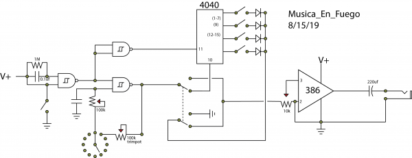
The switch on the far left shorts V+ directly to earth. That won't be good for your power supply. Possibly you need a high value resistor between the top of the switch and V+.
The DPDT switch in the centre shorts the outputs of the 4040 directly to earth which will probably destroy the 4040. Just leave that terminal of the switch un-connected.
That link from Pin 2 of the 386 to earth doesn't look good. Without checking the pin-out of the 386 I can't say what effect it will have but it could block the signal.
I'm not sure what the circle of dots at the bottom represents. As far as I can tell the trimpot should connect directly to the potentiometer.
Cheers! |
|
|
Back to top
|
|
|
PHOBoS
Joined: Jan 14, 2010
Posts: 5599
Location: Moon Base
Audio files: 705
|
| Posted: Thu Aug 15, 2019 6:21 am Post subject:
|
|
|
yes, there are several errors in that schematic which Steveg already mentioned. Maybe you've actually connected things differently, but I can only go by how it is drawn.
1. The button/switch creates a dead short between V+ and GND.
2. The capacitor and resistor connected to the other input of the NAND gate have no use connected like that. (have another look at the schematic I posted)
3. The DPDT switch does indeed short the outputs of the 4040 to GND.
You actually don't need a DPDT switch there, you could just switch the input of the LM386 amp between the output of the NAND oscillator or the 4040.
If you do use a DPDT switch I would add a pulldown resistor to pin 10 of the 4040, although that's not really needed in this case. Also you'd normally add
a pulldown resistor to the point where all the diodes are connected together but in this case the level pot for the LM386 already takes care of that.
The LM386 is actually connected ok, although it looks a bit weird how it is drawn. The circle of dots seems to be a rotary switch but there's nothing connected
to the other contacts so I am not sure what its function is, but maybe you have some plans for that.
_________________
"My perf, it's full of holes!"
http://phobos.000space.com/
SoundCloud BandCamp MixCloud Stickney Synthyards Captain Collider Twitch YouTube |
|
|
Back to top
|
|
|
|

 Forum index » DIY Hardware and Software » Lunettas - circuits inspired by Stanley Lunetta