| Author |
Message |
fsymes
Joined: Dec 21, 2019
Posts: 2
Location: Australia
|
 Posted: Sat Dec 21, 2019 6:22 pm Post subject:
Baby Trig Sequencer Newbie Question Posted: Sat Dec 21, 2019 6:22 pm Post subject:
Baby Trig Sequencer Newbie Question |
  |
|
Hey guys, it's my first time posting on this forum, please excuse me if I've posted this in the wrong place.
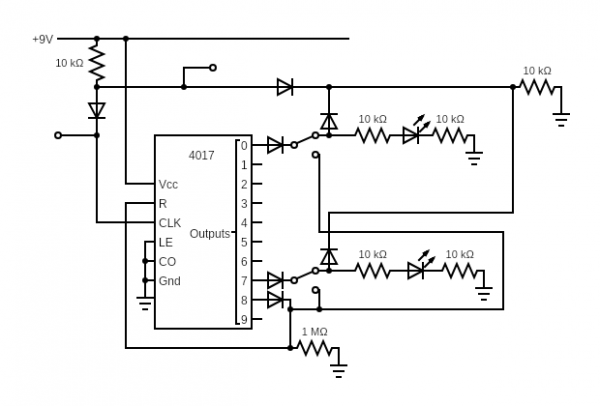
Attached (hopefully no mistakes) is the schematic for a baby 8 trig sequencer I'm kinda making up as I go along. Sorry for the awful drawing. There are 8 of the switch configurations attached to outputs 0-7.
The 8 switches are on-off-on, where one on connects them to the reset line, and the other connects them to the trig line. The trig line gets diode AND with the clock which then gets sent to a simple RC low pass gate.
The problem is this: when a switch is set to off, (or all switches are set to off) the output isn't zero, it's a low voltage clock pulse. I guess the clock is leaking into the trig line somehow. It means instead of the trigs opening and closing the LPG, they more like accent it.
So either I have soldered something badly and it's leaking that way, or most likely, I don't understand electronics very well. The pulldown resistors were supposed to fix this "floating lines" problem and they did ... but not in this case.
The diodes are all 1n4148 and there is a second sequencer running alongside this to handle the CV, clock is from a 40106. I don't think any of that is relevant but just in case.
Very grateful for any help, or any criticisms of the design. I'm making a simple synth as a christmas present for a child and I've bitten off a bit more than I can chew ...
| Description: |
|
| Filesize: |
19.07 KB |
| Viewed: |
113 Time(s) |
| This image has been reduced to fit the page. Click on it to enlarge. |
|
|
|
|
Back to top
|
|
 |
PHOBoS

Joined: Jan 14, 2010
Posts: 5603
Location: Moon Base
Audio files: 705
|
| Posted: Sat Dec 21, 2019 7:54 pm Post subject:
Re: Baby Trig Sequencer Newbie Question |
|
|
 
I think the problem is that you are using a diode OR to control a diode AND. It can work to some degree but not with the same resistor values.
If the switches are off and the CLK is low then it will pull the trigger output low (not entirely 0V because of the forward voltage of the diodes),
however, if the clock is high then the 2 10K resistors form a voltage divider so the output will probably be somewhere around 4.5V.
By increasing the value of the pullup resistor it should go lower. I did something similar before and I used a 200K pullup with a 47K pulldown but
that was to drive a logic gate and with a supply voltage of 12V. What values will work for you depends on what the LPG circuit has on the input.
Also, have a look at the "little gate" sequencer 
_________________
"My perf, it's full of holes!"
http://phobos.000space.com/
SoundCloud BandCamp MixCloud Stickney Synthyards Captain Collider Twitch YouTube |
|
|
Back to top
|
|
|
fsymes
Joined: Dec 21, 2019
Posts: 2
Location: Australia
|
| Posted: Sat Dec 21, 2019 8:04 pm Post subject:
Re: Baby Trig Sequencer Newbie Question |
|
|
| PHOBoS wrote: |
By increasing the value of the pullup resistor it should go lower.
|
Thanks for the reply, I'll give this a try and see how it goes. To be perfectly honest I used 10k there because it's my fallback value for "a resistor", there's no reason at all I chose 10k. I am very, very much still learning electronics.
Thanks for the link to a actual working version of the schematic lol, probably should have looked that up before I started randomly putting stuff together. Next time though! |
|
|
Back to top
|
|
|
|

 Forum index » DIY Hardware and Software
